The Railway Bridge at San Khayom: Summary
Note: a more detailed study of the San Khayom bridge is available as a pdf by email on request.
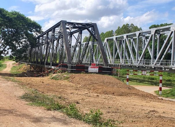
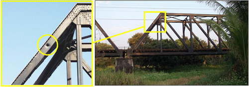
The old railway bridge1 at Ban San Khayom2 is noteworthy because it is one of the few structures remaining in northwest Thailand that displays damage resulting from air attacks during World War II.3 The old bridge has recently been replaced with a new structure of greater load capacity; however, the old bridge has not been demolished, but rather moved to the side and preserved:4
In the old structure, three distinct holes are visible. Unfortunately no documentation seems to exist, or at the least to be currently available, regarding the incident(s) that caused the damage.
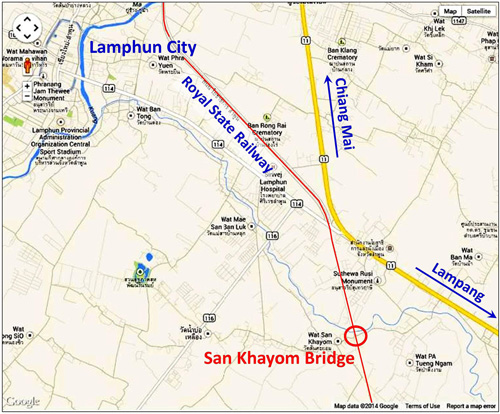
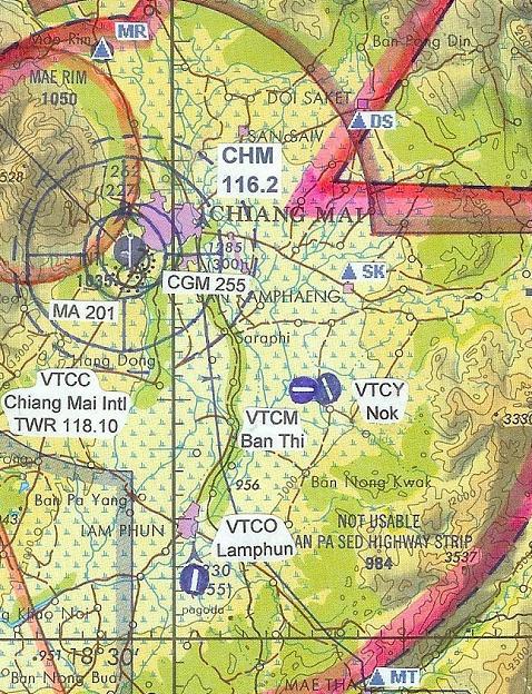
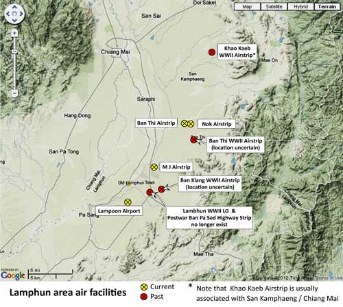
The local map below is current; however, in WWII, Thai Route 11 (shown in yellow) linking Chiang Mai, to the north, through Lamphun with Lampang, to the southeast, did not exist.5
An “all-weather” gravel road paralleled the railroad north from Lamphun to Chiang Mai (now Thai route 106). However, the route taken by the road heading southeast out of Lamphun towards Lampang is not clear. Close to Lamphun, it was judged by Allied intel to be poorly maintained and required large-wheeled oxcarts particularly during rainy seasons when very deep rutting would develop. Beyond that was an even rougher trail over the Khun Tan mountain ridge which divided the watersheds of Chiang Mai’s Ping River and Lampang’s Wang River.6
The Pratt through-truss railway bridges, old and new, at Ban San Khayom are located about 7 km southeast of Lamphun. Each consists of two 40m spans crossing the Nam Mae San (น้ำแม่สาน) (San Creek); the creek is not navigable:7

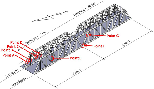
Damage Points on the Old Bridge8
Points A, F, and G are unquestionably shell holes; Points B, C, and D will be shown to be related to Point A. Point E, originally thought to be the result of a ricochet, on review, appears to have resulted from an object having fallen from a passing train and is not here discussed.
Dates for the damage at specific points cannot be determined with information currently available; however, it seems likely that the designated points (except E), were the result of military action, and the only such action in the area was during WWII.
Point A (Northerly Span 2, east side: U7L8-near midpoint of member)9
This is the first of three definite shell holes.
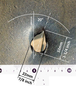
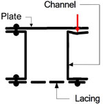
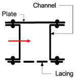
A projectile fired from north of the bridge passed through a 10mm (3/8 in) structural steel plate in the east leg of the north portal frame of Span 2:10

Looking south at the entry point for the hole at Point A; with dimensions added:11
The projectile passed through the bridge member and started to tumble as it continued through the truss.
Possible sources for the hole at Point A
The probable diameter of the shell that caused Hole A was 20mm,12 which suggests a projectile from a Hispano Suiza HS.404 derivative.13 The 20mm cannon was used on some or all versions of Hawker Hurricanes, Bristol Beaufighters, Lockheed P‑38 Lightnings, and de Havilland Mosquitoes.14
Hurricanes were recorded only once as having been in northwest Thailand, that as escort for a bombing mission over Chiang Mai on 06 March 1942, and it is unlikely that the sortie extended south past Lamphun to damage this bridge.15
Beaufighters were first reported by Shores in Thailand, 14 March 1944, (and confirmed by Brown)16 and thereafter frequently appeared in the record.
P-38s were first recorded by the USAAF Chronology17 over northwest Thailand on 23 April 1944 and were reported frequently thereafter.
Late in the war, an RAF program began to replace Beaufighters with Mosquitoes, but this latter aircraft did not see action over northwest Thailand.18
Thus the probable dates for the hole at Point A fall between March 1944 and August 1945, and, as can be seen, Beaufighters and P-38s are prime candidate aircraft.
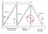
Point B (Northerly Span 2, east side: U7L7-near midpoint of member)19
The mark is on a 10mm (3/8 in) thick structural steel lattice or lacing strap in vertical built-up chord U7L7, between Panels 7 and 8. Looking south at Point B impact:20
The projectile arrived from Point A tumbling at an unknown rate. It rolled over the strap, carried by the momentum of the tumbling, to continue tumbling towards Point C on a slightly altered course.21
Point C (Northerly Span 2, east side: U6L6-near midpoint of member)22
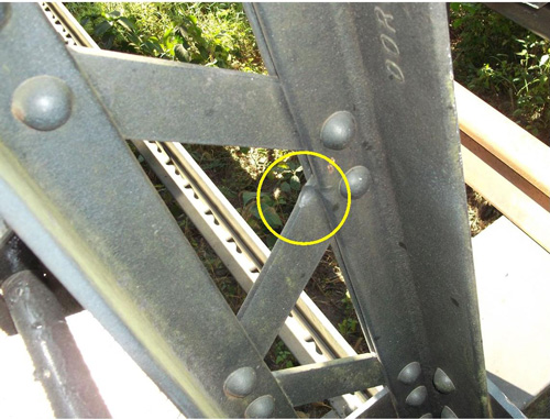
As with Point B, this mark is also on a 10mm (3/8 in) thick lacing strap; but it extends as well to an adjacent angle in the vertical chord, U6L6, of the truss between Panels 6 and 7. View of Point C impact, looking SSE and down:23
It may not be clear from the photo of the “entry” point, but the two marks are indentations, not “bubbles”. The nose of the shell left its mark on the intersection of a lattice strap and an angle. The projectile struck at such an angle that the impact did not stop its tumbling; rather that tumbling carried the projectile over Point C to continue towards Point D, with another slight alteration to course.
Point D (Northerly Span 2, east side: U6L5-near midpoint of member)24
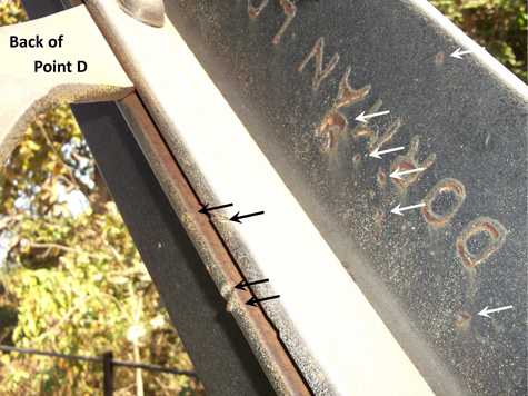
Again, as with Points B and C, the mark is primarily on a 10mm (3/8 in) thick structural steel lattice or lacing strap, but in lateral built-up chord U6L5 in Panel 6. Front view of Point D impact, looking SSE and level:25
At Point D, the base of the tumbling shell hit a lattice strap near its center — quite squarely. As a result, the rotational momentum of the tumbling was insufficient to rotate the shell over Point D and travel further into the truss. The strap was dramatic deformed by the impact and the projectile apparently shattered. Fragments resulting from the disintegration of the shell struck the structural angle on the opposite side of the built-up member:26
A review of the relationship of Points A, B, C, D
The projectile entered the easterly truss of Span 2 at Point A. Downstream Points B, C, and D are all within the confines of the truss. A string line connecting the four found no interferences with the crisscrossing lacing or lattice straps between the points. No evidence of the projectile’s movement beyond Point D was found:27
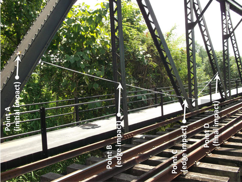
As is assumed in the individual discussions about Points A through D, the conclusion to be drawn is that the four points are directly related to the movement of one 20mm shell within and through the superstructure of the easterly truss of Span 2.
Point F (Southerly Span 1 west side: U7L8-near bottom of member)
This is the second of three definite shell holes.
A projectile fired from a northerly direction perforated a 10mm (3/8 in) thick structural steel plate and then stopped in a 16mm (5/8 in) thick steel channel leg directly behind the plate in the west leg of the north portal frame of Span 1. Looking southwesterly near the base of chord U7L8 in Span 1:28

Closeup of Point F:
Looking SSE at Point F, camera is approximately perpendicular to steel plate:29
The source is apparently a 20mm projectile, similar to that which produced the hole at Point A.30
Points A and F taken together
Both holes at the two points appear to be from 20mm projectiles. The positions and angles of the two holes suggest that the two projectiles could have come from a single source; ie, one gun during one flight over the bridge.
Point G (Span 1 West: U7L8-near top of member)31
This is the third of three definite shell holes in the bridge:
A projectile fired from generally WNW of the bridge passed through a 10mm (3/8 in) thick web of a structural steel channel in the west leg of the north portal frame of Span 1:32
The hole is not physically accessible without special equipment; thus a zoom lens was used to picture the hole, and its size was scaled from the photos. Looking ENE at shell entry hole in west side of Span 1:33
The diameter of Hole G is effectively 57mm.34 No Allied or IJAAF aircraft carried 57mm cannon in Southeast Asia during the war. The only gun of that caliber possibly available in that theater was a 57mm tank gun which would have been operated by the IJA or the RTA.
Points A, F, and G taken together
Unfortunately, there are no documents currently available to explain what caused the three shell holes at San Khayom bridge. In that absence, a scenario is constructed:
The holes at Points A and F are believed to have come from a 20mm autocannon mounted on either an RAF Beaufighter or a USAAF P-38. Since 20mm shells are inadequate to destroy steel truss bridges, that aircraft was probably strafing a train which happened at that moment to have been crossing the bridge. It is assumed that the two holes were produced during the same strafing run.
The projectile producing the hole at Point G was fired from a position roughly perpendicular to the bridge — and perpendicular to the course of the aircraft which produced the holes at Points A and F. The source of the shell that hit Point G could have been an IJA or RTA operated 57mm tank gun firing in an antiaircraft capacity at the Allied aircraft. The shell obviously fell short, hitting the bridge instead of the aircraft. That it did fall short could be considered consistent with the low muzzle velocity (offsite link) of an IJA 57mm tank gun, for which an operating gun crew might not have made proper allowance in its unconventional antiaircraft capacity. How and / or why such a gun became an antiaircraft weapon is not clear; however another weapon, also unconventional in antiaircraft defense, an antitank gun operated by the RTA, did bring down a B-24 during its approach to bomb the Kaeng Luang bridge, farther south along the Thai railroad on 21 November 1944.
| Condensed from larger article | ||
| Converted to WordPress by Ally Taylor | ||
| Updated, author errors & typos corrected | ||
- N18°32.300 E99°03.000 coordinates per Google Earth.[↩]
- Names in Thai, สะพานบานสันกะยบม, and English per Royal Thai Survey Department map 4846 III, titled “Lamphun”, Series 7018S dated 2007.[↩]
- Mark Robinson pointed out shell damage in the Lampang Railway Station which has survived intact. Aside from the Chiang Mai railway station, only some structures south of Lampang required repair or replacement. A subsequent 70 years of field testing vindicated railway engineering judgment which apparently determined the damage to be not structurally significant. The superficial nature of the damage to San Khayom Bridge no doubt saved it (Wisarut Bholsithi email of 2224 hrs, 03 Mar 2014).[↩]
- Photo by Nim via Line 14 Jun 2023[↩]
- “Terrain” map from Nations Online Project (no longer on-line). Annotations by author using Microsoft Publisher.[↩]
- Communications in Siam, French Indo-China, and Yunnan (Inter-Service Topographical Department (SSAC), 01 Mar 1945), Siam: Roads, p 7 (USAF Archive microfilm reel A8021: p0165).[↩]
- Photo looking NNE at SW corner of bridge by Jack Eisner, circa 2008.
Jack Eisner introduced me to the old bridge and its shell holes in Dec 2008 when I was assisting him search out the crash site of Jack Newkirk, a Flying Tiger Ace (the bridge was eventually found not to be related to events preceding Newkirk’s death).
More recently, the State Railway of Thailand (SRT) improved the pedestrian walkway cantilevered off the east side of the old bridge, which allowed Bob Edgar, a fellow retired engineer, and me to inspect the bridge more closely.
The old steel bridge was erected some time prior to the formal opening of the Northern Line on 01 Jan 1922. (per Wisarut Bholsithi email of 2224 hrs 03 Mar 2014).[↩]
- The spans are numbered per railway track stationing in this area, ie, increasing towards the north (left in the rendering).
Rendering looks southeasterly over northwest corner of bridge; by author using Trimble (offsite link) SketchUp. Annotations with Microsoft Publisher.
The view does not conform to the standard of north generally being towards the top of the page because here location of the “holes” dictates the view.[↩]
-
Point A:
 [↩]
[↩] - Both photos extracted from DSCF1824 of 14 Feb 2014.
The upright portion of the portal frame consists of a built-up section as shown; the red arrow indicates the projectile path into the section:
(sketch adapted from Bridge Inspector’s Reference Manual (Washington: National Highway Institute, 2006) Fig 8.1.6, p 8.1.6, by author using Microsoft Publisher).[↩]
- Extract from DSCF1722.jpg of 02 Feb 2014. Annotations done by author with Microsoft Publisher.[↩]
- Consensus of replies in various Internet forums queried about the holes in the bridge. However, Mark Robinson, in email of 15:37 22 Oct 2018, cautions that, in his experience, a bullet hole may be considerably larger than the bullet itself.[↩]
- Wikipedia Hispano-Suiza HS.404 (offsite link) notes that the gun was licensed to several manufacturers who introduced various modifications.[↩]
- Culled from “Users” in Wikipedia’s Hispano-Suiza HS.404 (offiste link).[↩]
- Shores, Christopher & Brian Cull, with Yasuho Izawa, Bloody Shambles, vol II (London: Grub Street, 2000), pp 288-289.[↩]
- Christopher Shores, Air War for Burma (London: Grub Street, 2005), p 180-181. Brown, AS, Silently in the Midst of Things (Victoria BC: Trafford, 2001), p 104. Shores first noted Beaufighter action by 211 Squadron, while Brown was in 177 Squadron.[↩]
- Carter, Kit and Robert Mueller, compilers, Combat Chronology 1941-1945 (Washington: Center for Air Force History, 1991), pdf p 364. USAAF 449th Squadron, using P-38s exclusively, is identified as flying missions over Thailand(Jackson, Dan, The Forgotten Squadron (Atglen PA: Schiffer Military History, 2010), pp 51, 93-95, 97, 144, 150).[↩]
- Wikipedia: No. 211 Squadron RAF (offsite link).[↩]
-
Point B:
 [↩]
[↩] - Extract from DSCF1770.jpg of 06 Feb 2014.[↩]
- Behavior of both shell and target when a shell hits the edge or near the edge of a target appears to be a separate subfield in ballistics. The concept of “edge effect” was introduced by EwingGreg comment of 1639 11 Apr 2014 in Delphi Forum: Military Guns and Ammunition (offsite link). Effect is discussed by Vanir Ausf B, 2335 17 Jul 2013, on Battlefront Forum: Combat Mission: Fortress Italy. (website live, but link lost).[↩]
- Point C:
 [↩]
[↩] - Extract from DSCF1782.jpg of 06 Feb 2014.[↩]
- Point D:
 [↩]
[↩] - Extract from DSCF2019.jpg of 27 Feb 2014.[↩]
- DSCF1800.jpg, dated 06 Feb 2014.[↩]
- DSCF2398.jpg of 03 Oct 2014, annotated by author with Microsoft Publisher. A practical note on stringing bullet paths: an earlier version of this view had a bright yellow, but very thin, rope that didn’t photograph well because it was too thin. This photo uses a much thicker rope which is much more visible (but it was not available in the ideal yellow color). However a curious mechanical problem arose during restringing the holes: the thicker rope visibly sagged from its own weight and it took some considerable cinching to take out the sags.[↩]
- Left photo extracted from DSCF1717 of 02 Feb 2014 and right photo extracted from DSCF1885 of 13 Feb 2014. Annotations by author using Microsoft Publisher.
As with Hole No. 1, the same portal frame detail applies; projectile path through section is shown as red arrow:
(adapted from Bridge Inspector’s Reference Manual (Washington: National Highway Institute, 2006) Fig 8.1.6, p 8.1.6, by author using Microsoft Publisher).[↩]
- Extract from DSCF2045.jpg of 17 Mar 2014. Annotations by author using Microsoft Publisher.[↩]
- However, again, Mark Robinson, in email of 15:37 22 Oct 2018, cautions that, in his experience, a bullet hole may be considerably larger than the bullet itself.[↩]
- Point G:
[↩]
- Both photos look ENE at north end of Span 1. Left: extract DSCF1717.jpg of 02 Feb 2014; and right: extract of DSCF1885.jpg of 14 Feb 2014.[↩]
- Extract from DSCF1718.jpg of 02 Feb 2014.
A similar steel channel, more accessible, was field measured elsewhere in the structure.
As with Point A, the same portal frame detail applies; projectile path through section is shown as red arrow:
(adapted from Bridge Inspector’s Reference Manual (Washington: National Highway Institute, 2006) Fig 8.1.6, p 8.1.6, by author using Microsoft Publisher).[↩]
- However, again, Mark Robinson, in email of 15:37 22 Oct 2018, cautions that, in his experience, a shell hole may be considerably larger than the shell itself.[↩]
